Arduino 2.4G Wireless RC Command with NRF24L01
I am building a RC sailboat from scratch. As I am a little crazy, I want to build the RC parts myself as well.
The idea is to drive a servo motor with an Arduino wirelessly.
The best chip to do wireless things easily is the nRF24L01 2.4GHz transceiver from Nordic Semiconductor. It is cheap and works seamlessly with Arduino platform.
Result
Here is a quick and dirty video of the result.
I will try to do a better one later.
Parts
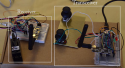
The idea is to build a transceiver and a receiver.
So for my first tests, I needed:
- 2 arduino boards
- 2 nRF24L01 modules
- 1 servo
- 1 joystick
- 2 batteries to power up everything.
I choose to go with Arduino Nano : it has a small factor but all Arduino Uno capabilities.
I use as well LiPo batteries with the LiPo Rider boards that allows a 3.7V to 5V conversion and the use of the USB port to power up the Arduino Nano.
Schematics
I skip the LiPo Rider and the batteries from the schematics as they are not relevant.
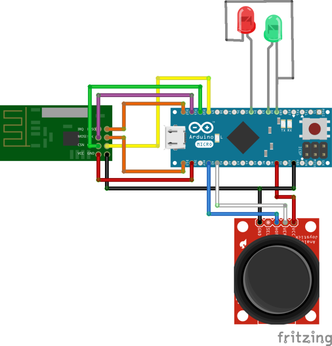
Here is the schematic of the transceiver:
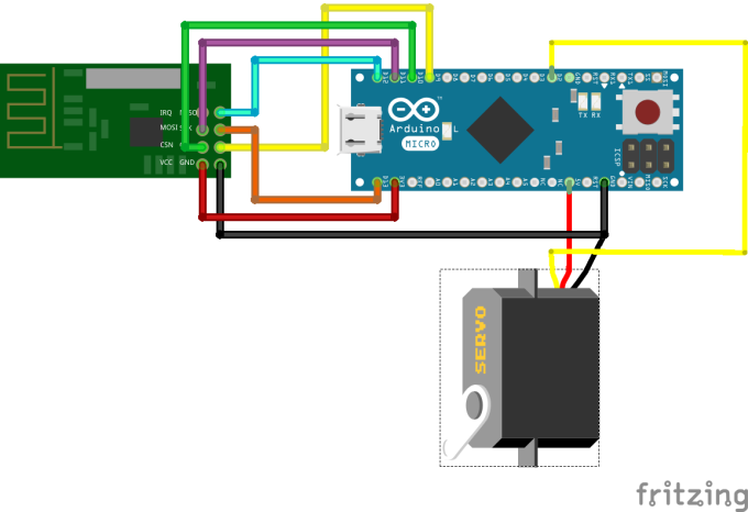
An the schematic of the receiver:
Tips
Servo steady point
The servo I used for the test is a 360-degrees continuous rotation servo.
As I only need 1 axis of the joystick for controlling the servo, I use the second axis to adjust the steady point of the servo.
Transmission status
I used 2 leds : 1 green and 1 red to show the status of the transmission.
Each packet transmit from the transceiver to the receiver has to be sent back to check the quality of the transmission.
If the value is sent back, the green led is on. If the timeout of the transmission is reached, the red led is on.
I can therefore easily monitor the quality of the transmission.
Code
Transceiver
#include <SPI.h>
#include "nRF24L01.h"
#include "RF24.h"
#include "printf.h"

//
// Hardware configuration
//

// Joystick Pins
int sensorPinX = A0;
int sensorPinY = A1;

// Led Pins
int red = 4;
int green = 2;

// Set up nRF24L01 radio on SPI bus plus pins 9 & 10
RF24 radio(9,10);

// Radio pipe addresses for the 2 nodes to communicate.
const uint64_t pipes[2] = { 0xF0F0F0F0E1LL, 0xF0F0F0F0D2LL };

//Default values
int sensorValueX = 0;
int oldSensorValueX = 0; // to keep track of the X value
int sensorValueY = 0;
int reposValue = 92; // default steady point for the servo


void setup(void)
{

  //
  // Setup and configure rf radio
  //

  radio.begin();

  // optionally, increase the delay between retries & # of retries
  radio.setRetries(15,15);

  // optionally, reduce the payload size.  seems to
  // improve reliability
  radio.setPayloadSize(8);

  //
  // Open pipes to other nodes for communication
  //

  // This simple sketch opens two pipes for these two nodes to communicate
  // back and forth.
  // Open 'our' pipe for writing
  // Open the 'other' pipe for reading, in position #1 (we can have up to 5 pipes open for reading)

    radio.openWritingPipe(pipes[0]);
    radio.openReadingPipe(1,pipes[1]);

  //
  // Start listening
  //

  radio.startListening();

  // Configure the LED
  pinMode(green, OUTPUT);
  pinMode(red, OUTPUT);
  digitalWrite(green, LOW);
  digitalWrite(red, LOW);
}

void sendOrder()
{
    // Get the value of the X axis of the Joystick
    sensorValueX = analogRead(sensorPinX);
    // We use thresholds on this axis : we only want a low value or a high value
    // if the previous value of the X axis is not over the thresholds, we can check the value of the current X axis.
    // this is to prevent redundancy
    if(oldSensorValueX > 35 && oldSensorValueX < 1000)
    {
      // If X axis is over the upper thresholds then we want to increment the value of the steady point of the servo
      if(sensorValueX > 1000)
      {
        reposValue++;
      }
      // If X axis is under the lower thresholds then we want to decrement the value of the steady point of the servo
      if(sensorValueX < 35)
      {
        reposValue--;
      }
    }
    // we update the previous value of the X axis
    oldSensorValueX = sensorValueX;

    // Now we get the value of the Y axis
    // The Y axis is used to drive the servo
    sensorValueY = analogRead(sensorPinY);
    // We have to map the Y value (from 0 to 1024) with the possible values for the servo (0 to 180)
    sensorValueY = map(sensorValueY,0,1024,0,180);

    // If the Y value is close (+-4) to the steady point we take then the value of the steady point.
    // This is to prevent noise around the steady point.
    if(sensorValueY > (reposValue -4) && sensorValueY < (reposValue+4)) sensorValueY = reposValue;

   // First, stop listening so we can talk.
    radio.stopListening();

    // Take the time, and send it.  This will block until complete
    bool ok = radio.write( &sensorValueY, sizeof(int) );

    // Now, continue listening
    radio.startListening();

    // Wait here until we get a response, or timeout (10ms)
    unsigned long started_waiting_at = millis();
    bool timeout = false;
    while ( ! radio.available() && ! timeout )
      if (millis() - started_waiting_at > 10 )
        timeout = true;

    // Describe the results
    if ( timeout )
    {
      // At this point the ACK did not arrived so the red LED has to be on
      digitalWrite(green, LOW);
      digitalWrite(red, HIGH);
    }
    else
    {
      // Grab the response, compare, and send to debugging spew
      unsigned long response;
      radio.read( &response, sizeof(unsigned long) );

     // At this point the ACK did arrived so the green LED has to be on
      digitalWrite(green, HIGH);
      digitalWrite(red, LOW);
    }
}


void loop(void)
{
    sendOrder();

}
Receiver
#include <SPI.h>
#include <Servo.h>
#include "nRF24L01.h"
#include "RF24.h"
#include "printf.h"

//
// Hardware configuration
//

Servo myservo;

// Set up nRF24L01 radio on SPI bus plus pins 9 & 10
RF24 radio(9,10);

//
// Topology
//

// Radio pipe addresses for the 2 nodes to communicate.
const uint64_t pipes[2] = { 0xF0F0F0F0E1LL, 0xF0F0F0F0D2LL };

// Default Values
int servoPos = 92; // Steady point of the servo

void setup(void)
{

  //
  // Setup and configure rf radio
  //

  radio.begin();

  // optionally, increase the delay between retries & # of retries
  radio.setRetries(15,15);

  // optionally, reduce the payload size.  seems to
  // improve reliability
  radio.setPayloadSize(8);

  //
  // Open pipes to other nodes for communication
  //

  // This simple sketch opens two pipes for these two nodes to communicate
  // back and forth.
  // Open 'our' pipe for writing
  // Open the 'other' pipe for reading, in position #1 (we can have up to 5 pipes open for reading)

    radio.openWritingPipe(pipes[1]);
    radio.openReadingPipe(1,pipes[0]);

  //
  // Start listening
  //

  radio.startListening();

  //
  // Dump the configuration of the rf unit for debugging
  //

  // The servo is attached to pin 2
  myservo.attach(2);
  // Start with the steady point of the servo
  myservo.write(servoPos);
}


void receiveOrder()
{
    // if there is data ready
    if ( radio.available() )
    {
      // Dump the payloads until we've gotten everything
      unsigned long message;
      bool done = false;
      while (!done)
      {
        // Fetch the payload, and see if this was the last one.
        done = radio.read( &message, sizeof(unsigned long) );

        // Use it
        // The servo can only ake a value fro 0 to 180
        if(message > 180) message = 180;
        else if(message < 0) message = 0;
        // Save the postion
        servoPos = message;
        // Write the position to the servo
        myservo.write(servoPos);
      }

      // First, stop listening so we can talk
      radio.stopListening();

      // Send the final one back.
      radio.write( &message, sizeof(unsigned long) );

      // Now, resume listening so we catch the next packets.
      radio.startListening();
    }
}

void loop(void)
{
  receiveOrder();
}
Credits
- fritzing.org for the great tool
- homautomation.org for the Fritzing parts
- maniacbug for the RF24 library